(Emergency-)Brake lights + blinker on my bicycle
On my cycle-commute there are a couple of places where better lights would come in handy. A year ago another biker drove into me, because I had to emergency brake.
So when a friend gifted me his left-over addressable LED stripe I was intrigued in how well this would work, as I had previously poured ours of work into making my own addressable LEDs using shift registers see my first iron man heart build. As it turned out, the LED stripe was super easy to use, after setting up FastLED.
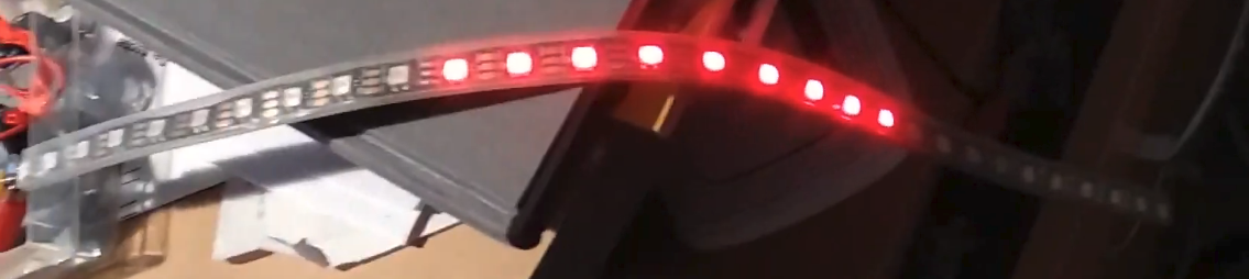
After turning the LEDs into a typical backlight configuration was easy:
My goal was to get a blinker and brake lights (including emergency brake lights). To get brake lights to work I saw three options:
- Put a button in the handbrake mechanism that triggers when I brake. A nice solution because it is an actual brake light.
- An accelerometer that measures deceleration. I didn’t like this option, because I feared acceleration might be harder to measure and even slight deceleration over a couple of seconds can be significant for following traffic.
- Measuring the electricity coming out of dynamo in the front wheel. This is a nice solution, as it should give me the exact speed of the bike.
I chose to try measuring the electricity out of the front wheel dynamo, because I didn’t find a trivial solution to detect braking in the handbrakes that could not in theory become a safety hazard (e.g. by blocking the brakes)
After looking up my dynamo model I found out that it produces electricity with a frequency of 28 oscillations per rotation. At a driving speed as little as 5km/h this produces up-flanks every 50ms. On the upper bounds, a speed of 50km/h has roughly 5ms between up flanks. Well within the limits of what a microcontroller can handle with ease.
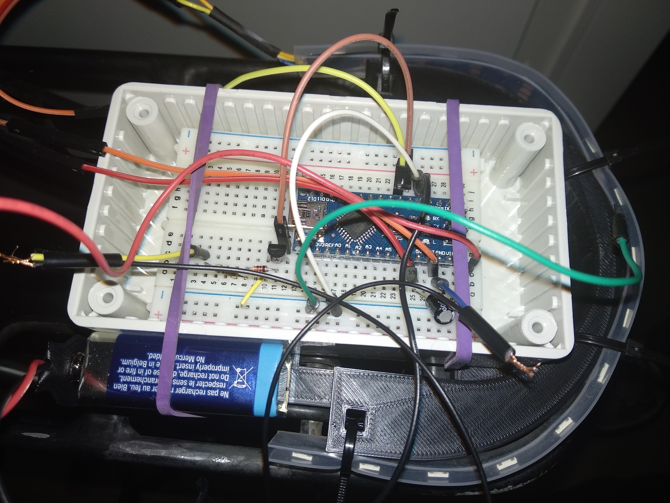
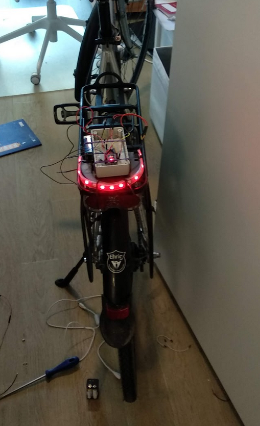
I quickly 3D printed a mount that would hold both the project box, as well as the LED stripe.
As the input signal from the dynamo could theoretically reach up to 60V, I used a zener diode and a transistor to protect the arduino. They share a common ground, which I don’t think is an issue for something as low-power as a bike light.
It took quite some time to get the code right to detect the braking correctly. It was the first time that I had used interrupts and I am not very familiar with working with that many globals in C. But after some time I thought I had figured it out. Albeit when I started testing it and having a run outside, it started detecting emergency brakes when I was pedaling very strongly. I wondered how that could be, as my code was working fine otherwise. It turned out that when I accelerate strongly, I pull the bike back, at some point in the rotation of the pedals. This is rightfully detected as a sudden deceleration of the bicycle.
The problem with this is that it “works as designed”. Only a true detection whether the brakes are engaged would help me here. So I ended up smoothing the signal by averaging by more then 100ms. This potentially increases the reaction time of the brakelight to >100ms, but still feels quite instant when looking at it. Now not every pothole and micro jitter is triggering the brake lights.
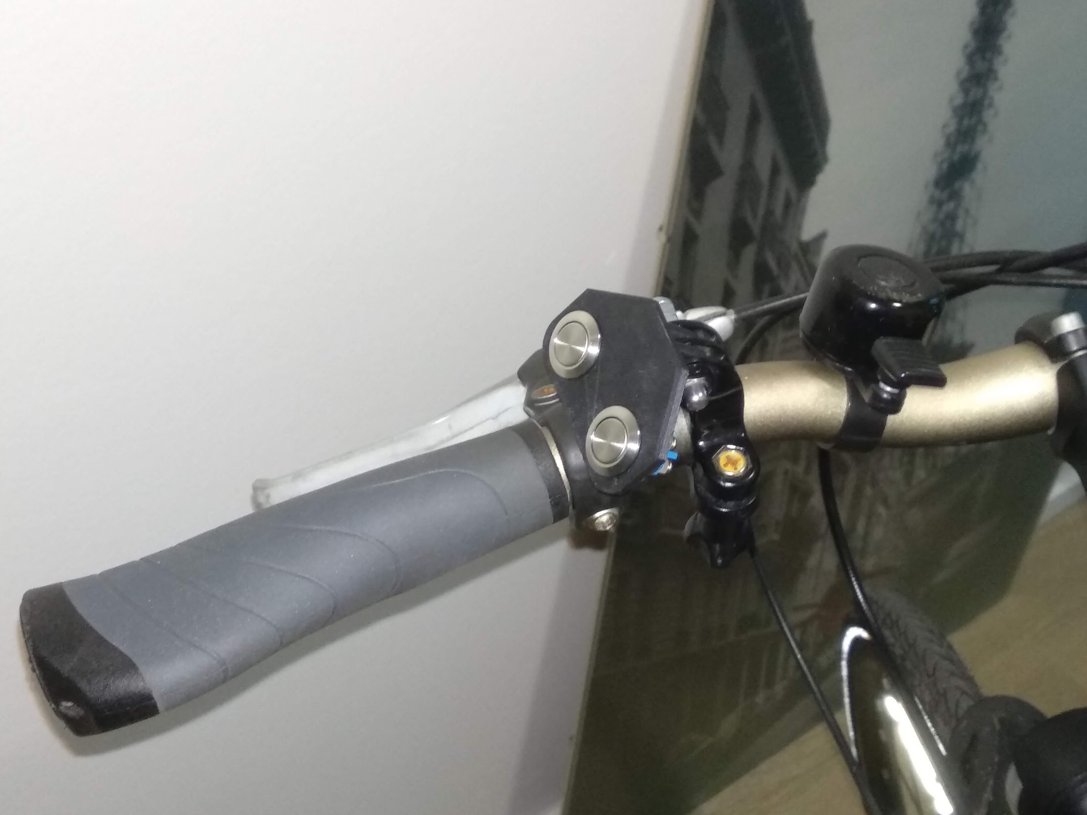
For the blinkers I needed some handy way to trigger them, so I 3D printed a button board that could be mounted using a GoPro mount:
The blinker automatically deactivates after some time, if a consistent speed is reached. This happens either, when you just have to change a lane, or when you accelerate after doing a right turn. It doesn’t automatically deactivate if you come to a stop shortly afterwards, e.g. because an intersection is blocked. This is quite handy, as I don’t have to worry about turning it off again.
And that’s it :)